Ghery,
Thank you for pointing out an error in the draft. Figure 12-2 shows up in the .doc version of the draft and somehow got removed in the conversion to pdf. I did not check the conversion close enough as it had worked on the previous draft and those before. This particular version used a new IEEE Template to get the front matter up to date.
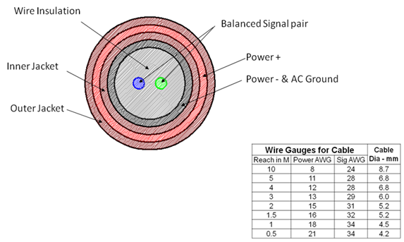
Figure 12-2 Possible UPAMD Concentric cable construction.
This figure was contributed by Foxconn in their study of the least expensive way to make a UPAMD cable.
In the case of the figure in the draft the shield on the twisted pair would be attached/terminated to the Vneg. In the figure 12-2 case, Vneg forms the shield around the twisted pair. This figure will need to be revised.
The actual termination is the 120 ohm resistance between the conductors at both ends of the line with the center tap returned to the Vneg lead at both ends.
Thank again for pointing this out.
Respectfully;
Bob Davis
Chair UPAMD/P1823
bobd@xxxxxxxx
408.353.5990 desk
408.857.1273 cell
bob.davis.scsi.com Skype
From: upamd-vote@xxxxxxxx [mailto:upamd-vote@xxxxxxxx] On Behalf Of Ghery S. Pettit
Sent: Thursday, August 30, 2012 6:26 PM
To: upamd-vote@xxxxxxxx
Subject: Comment on P1823 draft
All,
Pages 91 through 93 show that the communications channel is over a twisted shielded pair (see lines 24 and 25 on page 92). I see no way for this shield to be properly terminated using the planned connectors. What purpose will this shield serve without being terminated?
Ghery S. Pettit, NCE